Section 10-03: Speed Control System, Electronic — Aerostar, Ranger
| 1997 Aerostar, Ranger Workshop Manual
|
The speed control system consists of:
The system operates independently of engine vacuum, therefore no vacuum lines are required.
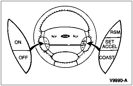
Speed Control Actuator Switch Assembly
It consists of:
Speed Control Indicator Light (Ranger Only)
Speed Control Servo
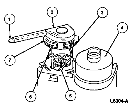
| Item | Part Number | Description |
|---|---|---|
| 1 | 9A825 | Speed Control Actuator Cable |
| 2 | — | Actuator Cable Cap
(Part of 9A825) |
| 3 | — | Seal (Part of 9A825) |
| 4 | 9C735 | Speed Control Servo |
| 5 | — | Cable Ball Slug
(Part of 9A825) |
| 6 | — | Cap Locking Tabs
(Part of 9A825) |
| 7 | — | Locking Arm (Part of 9A825) |
Stoplight Switch
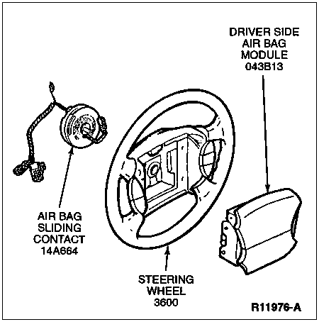
Air Bag Sliding Contact
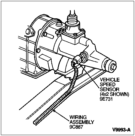
Vehicle Speed Sensor (VSS), (Ranger Only)
Deactivator Switch
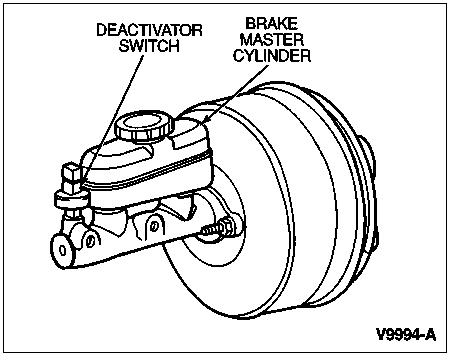
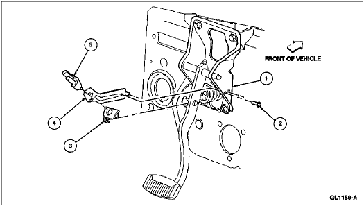
| Item | Part Number | Description |
|---|---|---|
| 1 | 2455 | Brake Pedal |
| 2 | N611173-S2 | Screw |
| 3 | 9C962 | Speed Control Vacuum Valve Actuator Adapter |
| 4 | 9A812 | Speed Control Bracket |
| 5 | — | Deactivator Switch |
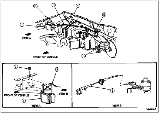
| Item | Part Number | Description |
|---|---|---|
| 1 | 9C735 | Speed Control Servo |
| 2 | N606689-S106 | Bolt |
| 3 | 9A825 | Speed Control Actuator Cable |
| 4 | N802768-SB | Clip |
| 5 | 9D726 | Clip |
| 6 | 9F924 | Deactivator Switch |
System Activation
To operate the speed control system, the engine (6007) must be running and the vehicle speed must be greater than 48 km/h (30 mph). Under these conditions, the system is activated by pressing the ON switch in the steering wheel. Then, the operator must depress and release the SET/ACCEL switch. This will result in the current speed being maintained until a new speed is set, the brake pedal is depressed, or the OFF switch is depressed. Only one switch button should be depressed at a time because the speed control system will accept only one command at a time.
Increasing Set Speed
Accel
A continuous depression of the SET/ACCEL switch will cause a smooth increase in vehicle speed. Upon release of the SET/ACCEL switch the new vehicle speed will be maintained.
The vehicle speed can be manually increased at any time by depressing the accelerator pedal and shaft (9725) until the higher speed is reached and stabilized, then depressing and releasing the SET/ACCEL switch.
Tap-Up
Current vehicle set speed may be increased 1.6 km/h (1 mph) by a momentary tap of the SET/ACCEL switch. Multiple taps of the SET/ACCEL switch will cause vehicle speed to increase in increments of 1.6 km/h (1 mph). For example, if currently set at 80 km/h (50 mph) then five taps will increase vehicle speed and set it at 89 km/h (55 mph).
Decreasing Set Speed
Coast
A continuous depression of the COAST switch will cause a smooth decrease in vehicle speed. Upon release of the COAST switch the new vehicle speed will be maintained.
The vehicle speed can be manually decreased at any time by momentarily depressing the brake pedal until the lower speed is reached and stabilized, then depressing and releasing the SET/ACCEL switch.
If vehicle speed is reduced below 48 km/h (30 mph) then the driver must manually increase the speed to over 48 km/h (30 mph) and reset the system.
Tap-Down
Current vehicle set speed may be decreased 1.6 km/h (1 mph) by a momentary tap of the COAST switch. Multiple taps of the COAST switch will cause vehicle speed to decrease in increments of 1.6 km/h (1 mph). For example, if currently set at 89 km/h (55 mph) then five taps will decrease vehicle speed and set it at 80 km/h (50 mph).
Resume
When the speed control system is disabled by pressing the brake pedal, the previous set speed may be re-established by momentarily depressing the RSM switch. The resume feature will not function if the system has been turned off with the OFF switch or if the ignition switch (11572) is turned off. If the vehicle speed has dropped below 48 km/h (30 mph) then RESUME will not function until the vehicle speed becomes greater than 48 km/h (30 mph).
Contact Assembly (Clockspring)
The contact assembly provides electrical interface between the steering column tube (3514) and the control switches in the steering wheel.